Application Notes
|
|
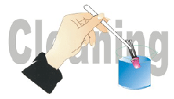
Cleaning
- Avoid using any unspecified chemical solvent to clean LED. For example, Trichloroethylene, Chlorosen, Acetone, and Diflon S3MC.
- Any cleaning method can only be taken under normal temperature in one minute or less if it is required.
- Alcohol is the one recommended for cleaning.
|
 |
| |
|
|
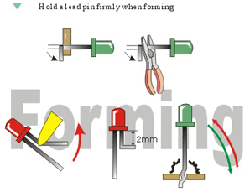
Forming
- Any forming on lead pin must be done before soldering, not during or after soldering.
- Avoid applying any stress to resin in order to prevent the epoxy fracture and break on bonding wire.
While forming, please use a tie bar cut or equivalent to hold or bend the pin.
- 2mm from the base of resin is the minimum distance for the place bending the lead pin.
- Avoid bending the lead pin at the same point twice or more.
|
 |
| |
|
|
Soldering
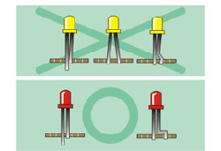
- Pin hole pitch on PCB must match lead pin pitch so as not to cause any stress on lead wires.
- No stress can be applied to lead pins when they are heated, otherwise disconnection may occur.
- Three minutes are necessary for LED to cool down to normal room temperature.
|
 |
LED General Information 1
HOW TO USE LED
- Please do not form the LED after soldering. If forming id necessary, it must be done before soldering.
- Any unsuitable stress applied to the epoxy may break bonding wires in LED.
- Soldering Bath ---260° ± 5 °C within 5 seconds: Soldering Iron-Under 30W within 5 seconds. (1.6mm from epoxy body)
- Do not apply any force of mechanical stress onto the leads or epoxy body during soldering heat is remained.
- If soldering one line of LED on a P.C .B. by using a soldering iron, don t solder both the leads of the LED at same time.
- Use Alcohol, Freon TE or Chlorosen to clean LED at normal temperature for less than l minute.
- Do not use unspecified chemical liquid because it may cause crack or haze on the epoxy body.
- In order to operate LED in stable condition, please put protective resistors in series.
- Resistor value can be determined by the formula
R = WHERE:
Vs = Source Voltage
VF = Forward Voltage
If = Recommended Current of LED (10-20mA)
- For the purpose of obtaining uniform brightness, LED shall be same current.
- It is useful for uniform brightness if you use larger source voltage and protective resistor.
- QUALITY CONTROL AND ASSURANCE¡PSAMPLING PLAN
U.S. Ministry of defense MIL-STD-105D level II(single sampling plans)
- INSPECTION ITEMS AND CRITERIONS FOR JUDGEMENTS
Measuring Methods for light Emitting Diodes (No.11830) and Light Emitting Diodes (No.11829) Stipulated by ministry of economical affairs of R.O.C.and by reference to Q.C. standards prevailing in prominent LED plants worldwide.
General provisions for Environmental s of CNS-Categorized electronic Parts, 3623-3634, 5637, 11233~11238, and U.S. ministry of National Defense MIL-STD-750 Specifications.
| CONDITIONS |
| THERMAL SHOCK |
LED placed in a chamber (-35°C) for 20 minutes, temperature increased instantaneously to +85°C for 20 minutes. The duration of the shall be for 10 complete cycles. (MIL-STD-202:107D) |
| HUMIDIY |
LED placed in humidity chamber which is maintained at 65°C, RH 95°C. The duration of the is for 96 hours. (MIL-STD-202:103D) |
| LIFE |
LED connected to a source of power and charged with 20mA at room temperature (25°C) for 1000 hours. (MIL-STD-750:1026) |
| SOLDERABILITL |
The pins of LED (1.6mm from body) dipped into tin which is maintained at 260°C ± 5°C. The duration of the is for 5 seconds. (MIL-std-202:208D) |
| VIBRATION |
LED paced on a vibrator which is maintained at 10-55 Hz/minute. 0.82mm amplitude. |
| PACKING |
LED packed in a corrugated fiberboard box and fallen freely on 6faces on 6 freely at a diagonal angle to the ground. The altitude of the fall be in the range of 229-609mm considering of the range of 229-609mm considering of the packed product. |
THE MEA SURING TERMS AFTER AND FAILURE CRITERIA AS FOLLOWS:
| MEASURE TERMS | FAILURE CRITERIA |
|---|
LUMINOUS INTENSITY (I V)
|
LOWER STAND ARD LIMIT X 0.5 |
| FORWARD VOLTAGE (V F) |
UPPER STAND ARD LIMIT X 1.2 |
| REVERSE CURRENT (I R) |
UPPER STAND ARD LIMIT X 2.0 |
LED General Information 2
ABSOLUTE MAXIMUM RATINGS
1. Test Condition For Each Parameter:
| Parameter |
Symbol |
Unit |
Test Condition |
| Reverse Voltage |
VR |
V |
|
| Reverse Current |
IR |
UA |
VR -5.0Volt |
| Forward Voltage |
VF |
V |
IF = 20mA |
| Luminous Intensity |
IV |
mcd |
IF = 10mA |
| Viewing Angle |
2Ø 1/2 |
Degree |
IF = 20mA |
| Spectral Line Half-Width |
Δλ |
nM |
IF = 20mA |
| Power Dissipation |
PD |
mW |
IF = 20mA |
| Peak Forward Current(Duty 1/10 1KHZ) |
IF (Peak) |
mA |
IF (Peak) = 150mA |
2. Absolute Maximum Rating: (Ta=25°C)
| Reverse Voltage |
5.0Volt |
| Reverse Current(VR-5V) |
≤100uA |
| Operating Temperature Range |
-40 °C ~ +80 °C |
| Storage Temperature Range |
-40 °C ~ +80 °C |
|

